
Matt Ferraro
CADmium: A Local-First CAD Program Built for the Browser
This project is discontinued. The github repos are still available as archives, but no deployment is maintained and no PRs will be accepted. You can still join the Discord if you want but it is not active.
We’re building a new open-source CAD program. We’ve gotten pretty far, but we need your help.
If you’d like to join the effort, join the Discord!
What Does It Take?
To build a 3D parametric CAD program, you need a:
- 2D Constraint Solver
- B-rep Kernel
- History Tracker
- 3D User Interface
- File Format
Let’s talk about each one!
2D Constraint Solver
This is the 2D engine that can ensure lines stay parallel or perpendicular, can make two circles have the same radius, etc.
The go-to approach to solving this problem is to concatenate all the unknowns into a big vector , then express every constraint as a linear equation and assemble them all into a big matrix equation:
Notionally, you can invert and you’re done!
In practice many optimizations are made. But this approach has downsides.
You can only invert if it is square, which gives rise to the conventional wisdom that all sketches should be perfectly constrained. If you have too many constraints, will be too tall and the approach fails, even if the redundant constraints are compatible.
If you have too few constraints, will be too short which means a solution can be found by inserting assumptions. But those assumptions are not always consistent with the modeler’s expectations. If you’ve ever had a sketch feature suddenly fly away to infinity, this is what happened.
Another downside is that solving this kind of matrix equation gets prohibitively slow when you have a lot of unknowns, which gives rise to the conventional wisdom that individual sketches should be small and simple.
There are many alternative approaches for constraint solving. Let’s try to formulate the problem as a 2D physics simulator:
- Each point has mass and velocity
- Each constraint is a spring that exerts a force on the points it is attached to
- There’s a friction force proportional to velocity
- Step the simulation forward some small until convergence
Instead of solving the whole problem at once, this formulation makes many small changes, driving the potential energy in the springs to zero.
At each time step, the runtime is linear with the number of springs and linear with the number of unknowns, so it may support dramatically more complex sketches than the textbook approach. This type of simulation lends itself to parallelization, so it may be very fast in practice. Maybe this step could happen in a compute shader?
In this formulation, overconstrained problems don’t complain about being overconstrained: a self-consistent system will solve normally, and in an inconsistent system the springs just fight it out and compromise.
Underconstrained problems don’t fly out to infinity, they find the nearest valid configuration.
Another advantage is that this formulation can support inequality constraints. You could constrain a length to larger than 1 cm and less than 2 cm, and preserve that degree of freedom for later. You could constrain a sketch angle to between 10 and 30 degrees.
More speculatively, you could extend this formulation to other types of forces. If a closed polygon should have a particular surface area, that could be accommodated as a pressure force.
There are other interesting formulations of the 2D constraint problem and there are certainly disadvantages to the spring-mass-damper approach, but in general we would advocate for solving the problem iteratively rather than in a single monolithic solve step. In the last decade there has been tremendous progress in solving gradient descent problems quickly, and in bringing the power of the GPU to the browser.
Our primary goal is to make a CAD experience that feels familiar for most CAD users, but we do believe there is room here for fresh ideas.
B-rep Kernel
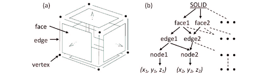
In Mechanical CAD, users need to interact directly with the edges and faces of their parts.
Consequently, all parametric CAD programs model parts by directly representing their boundaries in a data structure. A cube is representated as a Solid with six Faces, each with four Edges, each with two Points. This approach is called Boundary Representation, or b-rep.
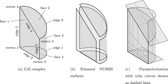
For curved surfaces, it is common to use a generalization of splines called NURBS surfaces, which allow the user artistic control over freeform shapes, and the ability to represent conic sections exactly.
Representing shapes this way is hard, and it gets dramatically harder when you try to implement boolean operations like Union, Intersection, and Subtraction. A library that handles this kind of data and boolean operations is called a b-rep kernel, and they are extremely difficult to make.
Each of the big four CAD companies has written their own, and it took them decades. Today’s proprietary CAD landscape looks like this:
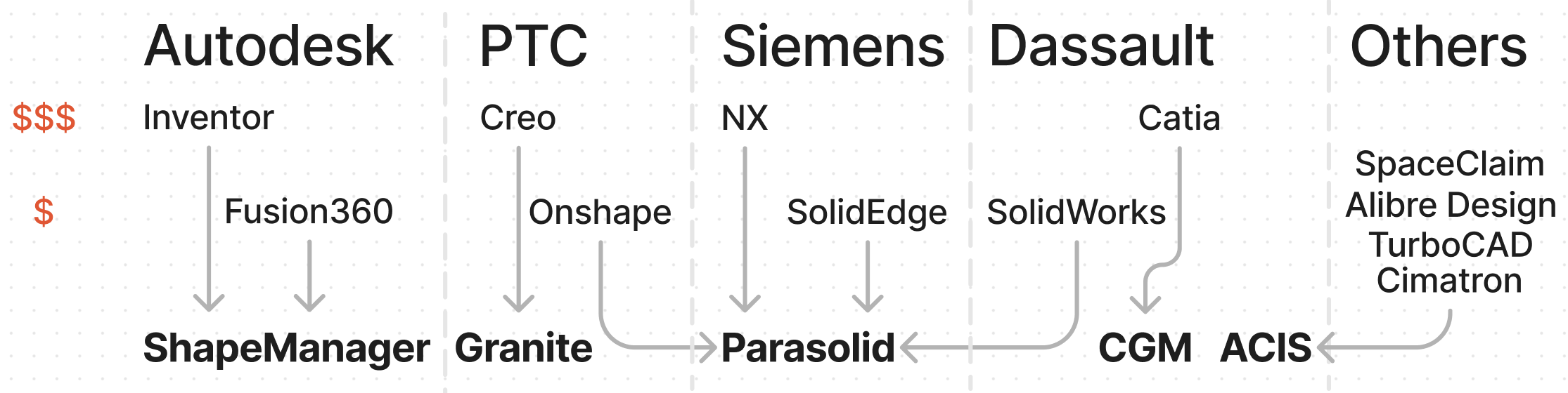
Where the company is at the top, the b-rep kernel is at the bottom, and in the middle are some of the CAD programs they offer, arranged loosely by cost.
The most important b-rep kernel is Parasolid which powers a lot of the industry including products like Shapr3D and Plasticity. Parasolid is the Cadillac Escalade of b-rep kernels: It is huge, expensive, and it offers every amenity you could ask for as well as a bunch of amenities you didn’t ask for.
In contrast, the open source CAD landscape looks like this:
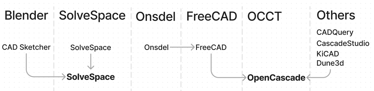
The only popular open-source b-rep kernel is OpenCascade, which is the Pontiac Aztek of b-rep kernels: It is ugly, barebones, and it might break down on you, but it is drivable and you can get one for free.
SolveSpace is a Tuk-Tuk in that it was built by one person in a garage and it gets a lot done with very little, but it only looks like a car if you squint.
All this to say: The proprietary kernels are good but expensive and the open-source kernels are free but not good.
All popular b-rep kernels are old and written in C++. If you consult the official build instructions for OpenCascade, you see this screenshot:
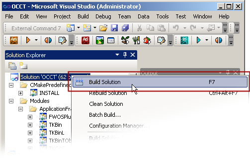
Which looks like it was taken on Windows 2000?
Thankfully, there is a new open-source b-rep kernel being developed right now called Truck! Unlike every other b-rep kernel, this one is modern and it is written is Rust.
Rust is not categorically better than C++, but it is better in a lot of ways that matter to an open-source project. Its build tooling is powerful, convenient, and well-documented. It has centralized package management. It provides more guarantees around memory safety which in turn makes parallelization easier and safer. Its compiler errors are friendly and helpful, so Rust code is easier to refactor. Importantly, Rust has excellent support for compiling to webassembly so it can be readily run in a browser.
It is trivial to include Truck in any Rust project. It runs on any operating system and in a browser. They even provide javascript bindings and examples!
Truck is about four years old and it already covers all the basics. It can read and write .step files. It can triangulate surfaces to a fixed tolerance. It has NURBS support. It can compute the Intersection or Union of two Solids*, as well as the Not of a single Solid.
It is small and lightweight, it is being developed by a real company, and it is young enough and simple enough that a few motivated people could add major pieces of functionality, in a fork if necessary.
For example, the B in NURBS stands for B-Splines, but there is an alternative representation called T-Splines which is better in some ways. The patent on T-Splines is owned by Autodesk, but it just expired a few weeks ago! Support could theoretically be built into Truck!
I think that Truck is the Rivian R3 of b-rep kernels: It is smaller than its cousins, it’s using a lot of modern technology in an exciting but proven way, and it isn’t quite finished yet! At the risk of overextending the metaphor, Rust is the electric motor and C++ is the internal combustion engine.
History Tracker
Parametric CAD programs store the Feature History of your design. You sketch, extrude, and revolve until your part is done. What makes it “parametric” is that you can also rewind the clock to an earlier step, change something about it, then replay your features to get a slightly different part.
Abstracted further, you can inject variables as inputs to the model, then change the values and the part will update. Your model has now been “parameterized”.
This approach has been wildly successful, but it’s often brittle and there are valid criticisms of the whole paradigm.
One approach that has emerged to help address the brittleness of parametric CAD is called the Resilient Modeling Strategy, wherein:
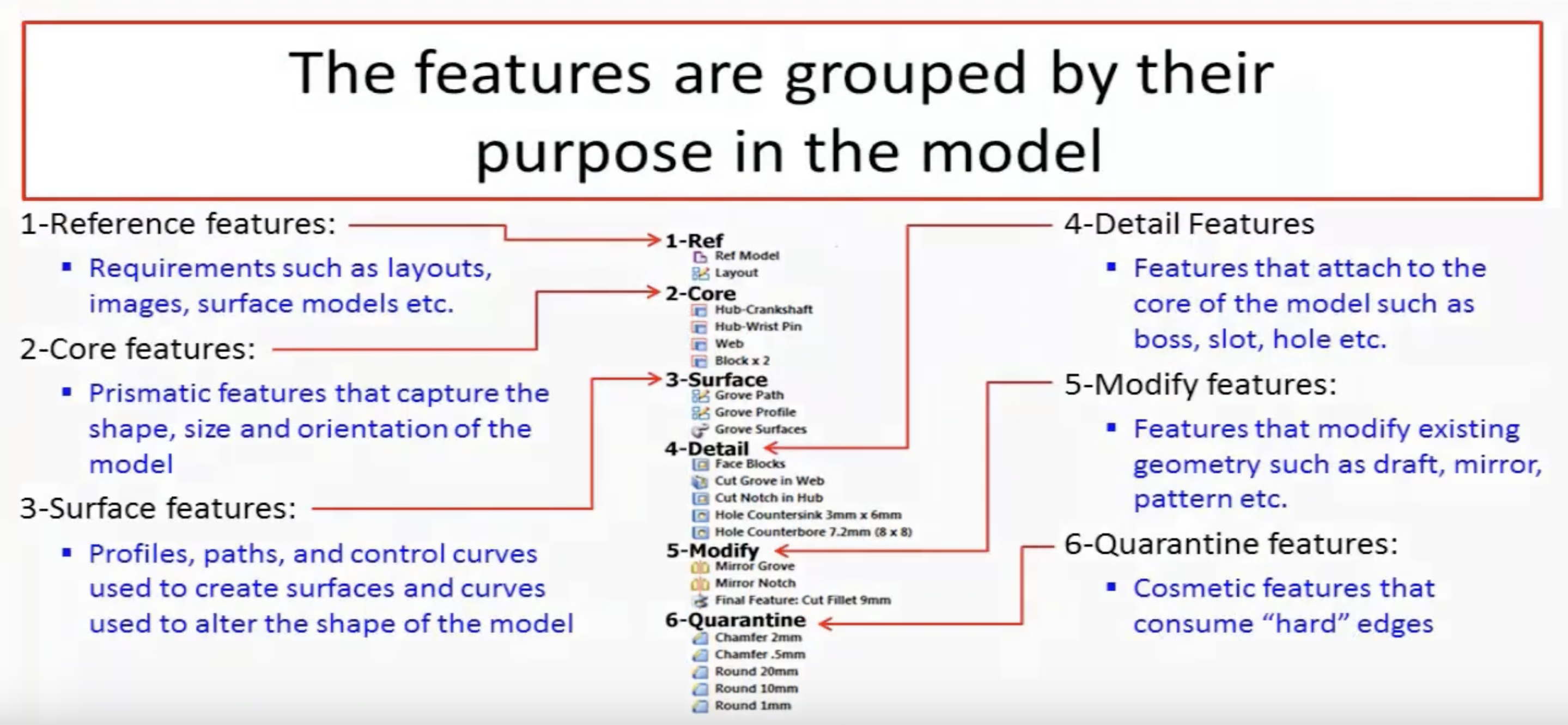
RMS is a set of conventions for how parts should be designed. For example, all chamfers and fillets go last because they consume edges. Detail features are allowed to reference Core features, but not each other, and so on.
Maybe there is value in enforcing these patterns within the CAD program. It may feel limiting at first, but it may pay huge dividends by making designs actually reusable and transferrable.
Another avenue to explore could be adding a feature history to sketches. In today’s CAD programs it’s common to sketch base features likes circles and rectangles, then use tools like mirror, linear pattern, or sketch fillet to duplicate or modify those features. Then you sketch more base features and use more tools, back and forth. The web of dependencies this builds in a sketch is very hard to understand if you weren’t the one who made the sketch, so it is often faster to delete the whole sketch and start over.
But if sketch features were also stored and displayed in a feature tree, then the ideas from RMS could be applied to a single sketch. Reference features like projecting an edge probably should come first, and final details like snipping and filleting should probably come last.
Again this might feel limiting at first, but putting an operation first in the feature tree doesn’t mean you have to start with that feature chronologically as you sit down to model.
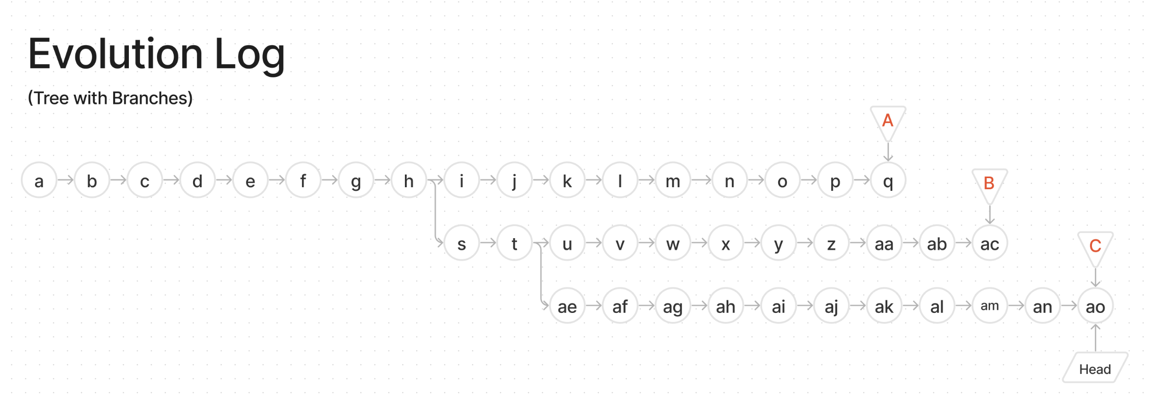
On the topic of chronological ordering, why not record every user event in an append-only log? If that log were the single source of truth for the file, then any particular Feature History could be reconstructed by moving a time slider. Think: Unlimited Undo/Redo, even after closing and reopening the file:
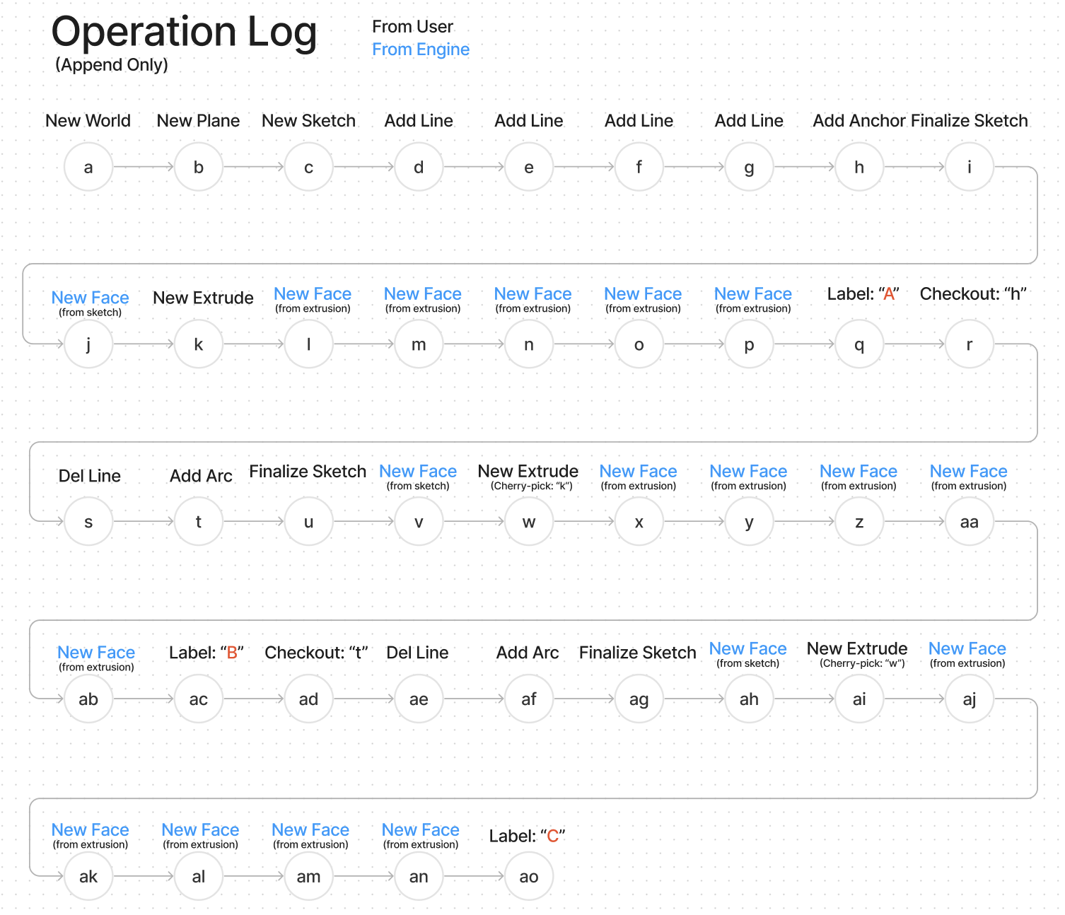
You could imagine rewinding back to an earlier version of the Feature History and forking off in a different direction to try the design a different way. You would end up with a branching tree of different attempts, exactly like a git history:
Our goal is to create a CAD application where every valid document state is trivially recoverable. Every false start, every “final” deliverable, whether you knew you needed it or not.
With that machinery you could maintain different variants of parts and keep a record of every design as it was when you ran downstream processes like toolpath generation or FEA.
If building this version control system is akin to building git for Mechanical design, could we also build github for Mechanical design?
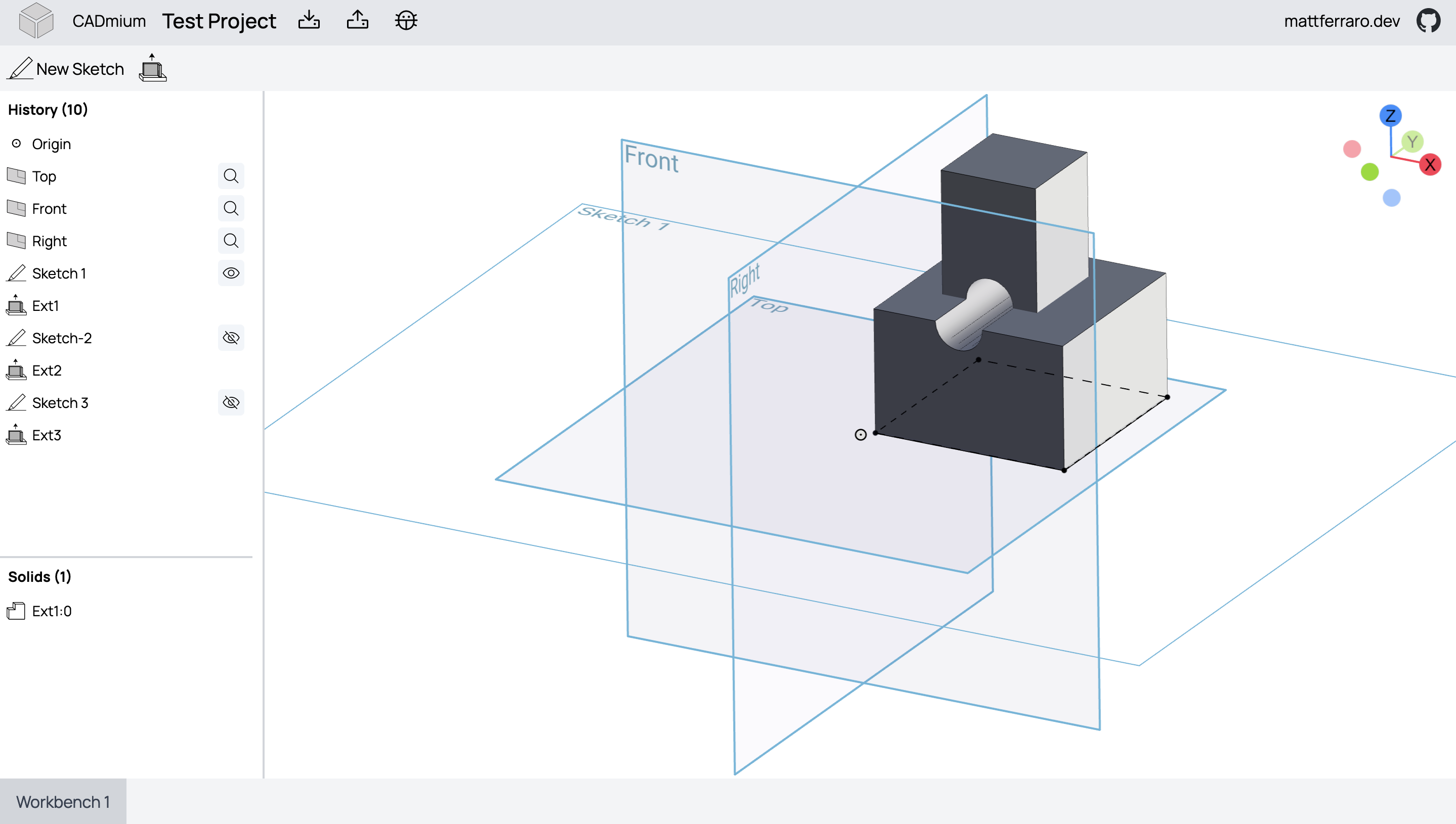
3D User Interface
We love the idea of doing CAD in a browser. Onshape paved the way here and it’s awesome.
However, Onshape doesn’t really run in a browser—it runs on a GPU enabled cloud instance somewhere in AWS and streams the results to your browser. This is why if your internet connection goes down while you’re using Onshape, you literally can’t do anything. You can’t even rotate the viewport.
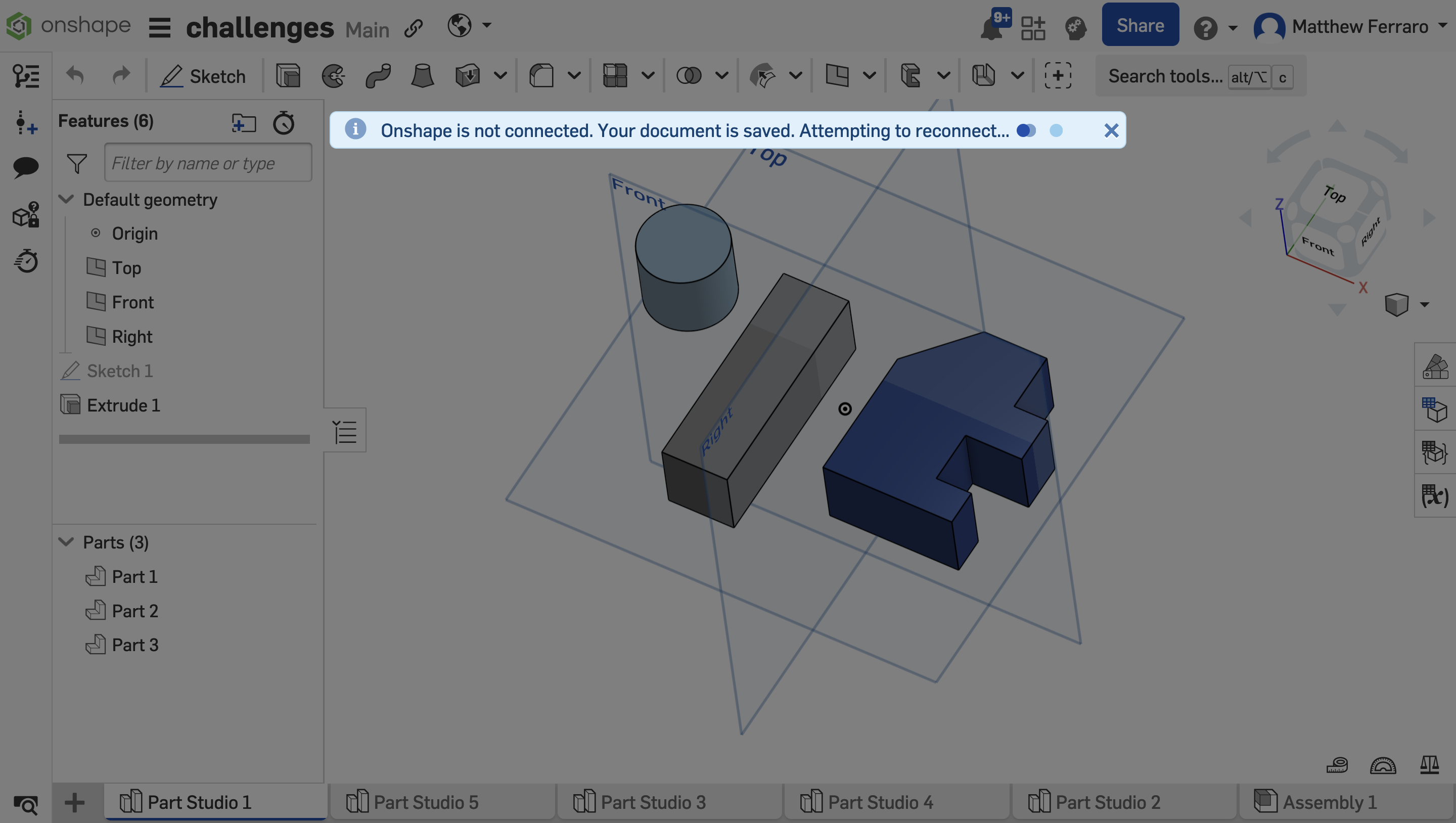
But CADmium doesn’t have to be like that. Given that Truck can compile to webassembly, CADmium can do everything right there in your browser. A Local-First app!
We’ve been using this tech stack:
- Three.js for the 3D viewport
- Svelte for state management/reactivity
- Threlte to bridge the gap between Svelte and Three.js
- Message passing between the UI and the b-rep kernel, rather than sharing memory
- Electron for running locally
- Bog standard everything else: Typescript, TailwindCSS, Vite, etc
This kind of stack allows the entire app to be written in a reactive, declarative way, plumbing data changes all the way through to mesh updates without you having manage that complexity. That’s important because 3D CAD apps are among the most complex UIs that exist. If you want to make a good one and you only have a small team, the framework had better do a lot of heavy lifting!
With this stack we were able to build a proof of concept that works, so we feel that this won’t be the limiting factor for CADmium.
File Format
CADmium will use JSON for everything.
The Operation Log mentioned above should be JSON lines. And after you’ve designed a part, CADmium should support exporting to an even simpler exchange format. Notionally something like:
{
  "steps": [
    {
      "type": "sketch",
      "id": "Sketch-01",
      "data": { ... }
    },
    {
      "type": "extrude",
      "id": "Extrude-01",
      "data": {
        "distance": "10mm",
        "sketch": "Sketch-01",
        "faces": [0],
        "type": "new"
      }
    }
  ]
}
Which could be converted into a .step or .stl using the CADmium command line interface (CLI):
$ CADmium export my_part.cadmium --format stlThese two ingredients:
- A simple, easy-to-understand file format
- An open-source CLI to work with it
Are what’s required to enable an ecosystem that can create tremendous new value that we would never be able to build ourselves.
Imagine being able to pop open a text editor to change an extrusion depth or a fillet radius. Imagine writing a script that replaces all the M5 screws with M6 screws, without having to read a nasty spec.
What would a change like that look like using git-diff?
I mentioned above the concept of github for Mechanical design. If such a thing really were built and people really did use it, then it would not be hard to imagine building github copilot for mechanical design.
We don’t know what that would look like in practice, but we think it’s fair to say that large language models work best on simple, open, text-based formats rather than complex, proprietary, binary formats.
Conclusion
Of the ideas mentioned here, we have no idea which ones are going to work out and which ones will turn out to be duds. But we know that somewhere in this space, there’s a huge opportunity for a small group of people to make an outsized impact on the manufacturing industry.
These are the things we need help with:
- Programming in Rust (general improvements)
- Computational Geometry (patches to Truck)
- Three.js help (new camera controller, better lighting, post-processing)
- Finding grant opportunities or wealthy benefactors
These are things that we are not touching for now, but would love to revisit later:
- Venture Capital
- Toolpath generation (CAM)
- Finite Element Analysis (FEA)
If you find these ideas intriguing, please join the CADmium discord server and chat with us!