
Matt Ferraro
Anatomy of a CNC Router

This is the encyclopedic blog post I wish I could have read when I started designing my CNC router.
I’ll cover all the components and some of the design considerations you’ll need to keep in mind when desiging your own CNC router.
Table of Contents
- Overall Layout
- Frame Construction
- Linear Guides
- Linear Actuation
- Motors
- GCode Interpreter and Step Generator (GRBL Variants)
- GCode sender
- Full Motion Control Solutions
- Spindle
- Work Holding
- Dust Collection
- Axis Arrangement
- Cutting Tools
- Usability Improvements
- Conclusion
- Contact me
Overall Layout
The foundation of a CNC router is some sort of rigid frame. On top of the frame you attach linear guides which allow your axes to move. You actuate that movement with belts or screws, whose rotation is powered by motors. Those motors are controlled by a pulse generator attached to a gcode intepreter, which gets its commands from a gcode sender. I’ll cover all your major options below.
Frame Construction
The frame is the main body of your machine. You should use the most rigid material you are able to work with.
Wood

If you only have access to woodworking equipment, then wood is your only choice. The main advantages of wood are that it is cheap and easy to work with. The main disadvantage is that wood is not rigid enough to resist cutting forces, leading to chatter and low-quality surface finishes. A secondary concern is that wood is very dimensionally unstable, easily fluctuating with temperature and humidity changes.
If you never intend to cut any material harder than wood and you are comfortable never achieving tight tolerances or repeatable dimensions, a wooden frame can be a very economical choice. If you are primarily making art pieces rather than functional mechanical parts subject to tolerances, this might be a good choice for you.
Metal tube with 3D Printed Joints

The Mostly Printed CNC and others like it make use of cheap extruded metal tube to serve as bones and 3D printed parts to serve as joints. Many of these designs don’t require metalworking skills of any kind except to cut metal tubes to length. Given the ubiquity of 3D printers nowadays, these designs are extremely accessible, maybe moreso than wooden designs.
Their primary weakness is that 3D printed parts aren’t very rigid, so the precision, repeatability, and surface finish of parts created on these machines is limited. Another common weakness in these designs is to use the extruded metal surface as the linear guide. Extruded metal is not a precision surface so any surface imperfections in the metal will translate to imperfections in the finished work. This limits the usefulness to hobby and art projects.
I should mention that “low-precision” for a CNC router might mean give or take 30 thousandths of an inch. If you are a woodworker used to table saws and pencil-drawn lines, tolerances that tight are fantastic and either a wooden frame or mostly printed frame will likely exceed your needs.
Extruded Aluminum aka 8020

A very popular choice for router frames is aluminum 8020. The extruded profiles can be ordered in many dimensions and some providers like Misumi will not only cut them to length for you, they will drill and countersink holes, they will tap ends, and perform many other operations for you right in their factory.
The ease of working with 8020 cannot be overstated. If you have a miter saw you can easily cut it to length yourself to produce whatever design you like. The main advantages are that you get the rigidity of metal-on-metal joints and the infinite reworkability of a lego set without the difficulty of more traditional metalworking.
Some providers can even mill precision surfaces onto your extrusion, allowing it to play double duty as a structural member and a linear guide.
The main disadvantages of 8020 are that it is more costly than extruded aluminum tube and that it isn’t as rigid as steel. Still, it is a very popular choice because it is the cheapest, easiest way to produce a machine capable of hitting tolerances and producing great surface finishes.
Steel Beams

A Steel frame is a fantastic choice for its high mass and high rigidity. The biggest downsides are that metalworking requires tools that many hobbyists don’t have access to, and that steel frames do not damp vibration well.
If you are comfortable cutting, welding, and powder coating steel then you should probably go ahead and build the frame out of steel. Some large surfaces will need to be milled flat to hold linear guides, so make sure you plan everything out before you start welding.
With a steel frame you can hit tight tolerances and cut almost any material. Your machine’s primary limitation won’t be its frame. See This Old Tony’s excellent steel-framed CNC router build here
Cast Iron

Mills and lathes very often have frames made of cast iron for its superior vibration damping, extreme rigidity, and reduced part count by combining many parts together into a single casting.
This technique requires a tremendous amount of pre-planning, experience, and access to a metal foundry. It is prohibitively expensive and difficult for most hobbyists, but it produces some of the finest CNC machines that can be produced.
Other disadvantages are that cast iron parts can easily rust in open air or corrode if attacked with solvents. Cast parts generally need to be sand blasted and painted to survive industrial environments.
The casting process does not leave you with precision surfaces, so surface machining will be required on any parts that must be within a specified tolerance.
There is significant upfront engineering cost to produce the required molds, but once you have molds the per-unit cost of casting can be cost competitive. If you are designing an extremely high quality CNC router specifically to be mass produced and sold to others, consider cast iron for your frame.
Epoxy Granite

An exotic choice for frame building is epoxy granite—crushed up natural granite suspended in an epoxy binder that you cast into whatever shape you want, at room temperature.
The advantages of epoxy granite are that it is very dimensionally stable, it is resistent to chemical solvents, it does not require painting, and it can damp vibrations up to 30 times better than an equivalent steel frame, or 10 times better than cast iron. Epoxy granite can be cast into any shape you like using only at-home equipment and techniques. Pre-made threaded inserts and linear guides can be inserted at casting time, greatly reducing the need for machine finishing the final cast parts. For ultra high precision builds, epoxy granite is a fantastic choice.
The disdvantages are that epoxy granite has low tensile strength, and generally needs to be quite thick in all parts of the frame.
Epoxy granite is a rare choice among hobbyists, but I believe it is mostly because the design and build process are so foreign. Frames made from steel beams are easy to visualize and intuitive to link together. Frames made from cast material require a very different design approach that is just not well understood by most hobbyists.
If you are really looking to build an incredibly high performance machine, especially if you plan to make many machines, epoxy granite might be a good choice for you.
Linear Guides
The role of the linear guide is to constrain movement onto a single axis, preventing any unwanted rotation or deflection. These are often some of the most expensive parts on a CNC router.
Box Ways or Dovetail Ways

Mills and lathes generally use box ways or dovetail ways, which are precision machined surfaces floating over each other on a microscopically thin film of oil, kept tight with a small insert called a gibbs. When kept clean of damaging debris and maintained properly with oil, ways do not wear whatsoever and will last longer than every other part of the machine.
Ways have the advantage of a huge contact area, allowing vibrations to couple very effectively across the linear guide and into the frame. This allows vibrational energy to spread out through the entire machine body where it can be dampened effectively.
They carry the secondary advantage of being extremely massive, which helps reduce the amplitude of vibrations. Ways are the most rigid linear guides available. In mills or lathes the ways can be ground directly into the body of the machine, reducing assembly complexity and part count.
Despite all these advantages they are almost never incorporated into CNC routers because they are too expensive per unit length, their large mass makes them unweildy, and their wear patterns are not a good match for computer controlled machining.
The issue with wear is that if a small problem does develop on the ways, it can quickly cascade into a serious issue that causes further damage. Repairing ways, especially in situ, is a tremendously tedious and therefore expensive process. A human machinist is likely to notice such problems developing on a manual mill, but the computer operating a CNC mill will not notice.
In contrast all following linear guides are cheap and easy to replace when worn.
Supported Shafts

Supported shafts are precision ground steel with aluminum support structure underneath that allows you to fix the shaft firmly to the frame of the CNC machine. The linear bearings that run on the shaft are free to rotate about 20 degrees back and forth on the long axis of the shaft, meaning they actually offer two distinct degrees of freedom, one of which must be further constrained by some other aspect of your design. The bearings are usually easy to remove and replace.
These shafts introduce a lot of separation between the fixed surface and the moving surface, giving you space to put lead screws, run wires, or access the back side of the movable part. The disadvantage of extra separation is that it makes lever arms longer, amplifying torques on the frame.
Ground Rails

Precision ground linear rails are much lower profile than supported shafts. Their short height allows you to produce a much more compact design which can be good for rigidity, but the lack of space can make it difficult to fit a lead screw.
Also if you get this type of rail, be very careful never to remove the slides from the rail. The ball bearings inside will fall out and get everywhere. They are difficult to put back inside if you can even find them all.
Unsupported Shafts

Very cheap, low-quality builds will use unsupported linear shafts which are held only at two points. This is a terrible idea because the deflection for a given force is several orders of magnitude larger, leading to very low precision and lots of chatter, which leads to poor surface finish, slower cutting speeds, and shorter tool lifetime.
This solution works for laser cutters and 3D printers where tool forces are negligible, but this approach is inadequate for a CNC router. Despite the drawbacks, many cheap designs still use this type of linear guide. Avoid this if at all possible.
The one exception to this rule is if you design in much thicker shafts than would otherwise be used. A 2” diameter unsupported shaft may well be more rigid than a 1/2” diameter supported shaft, provided the end supports are also extremely strong.
Linear Actuation
The job of the linear actuator is to turn rotational movement into linear movement in order to propel the axes along their linear guides. Your main concerns are backlash, price, maximum length, backdrivability, and mechanical reduction. Secondary concerns might include resistence to wear, dust, and vibration.
Belt Drives

Belt Drives are extremely inexpensive, lightweight, and their cost is not dependent on the length you want to actuate. Very cheap ones do have a tiny amount of give under load and they may stretch a little over time, but not over the course of a single job.
Some designs feature a fixed motor with a moving belt that shuttles a linear stage back and forth. This can lead to belt flapping or bouncing unless you find a way to dampen belt vibrations.
An alternative approach is to use a fixed belt with your motor on the moving stage, as seen on the popular Shapeoko router. This allows you to trade a belt-bouncing problem for a cable routing problem, to power the moving motor.
Backlash can be a problem with belts if your pully and belt teeth don’t mesh perfectly. Another problem with belts is that there is no mechanical reduction between the motor and the gear that moves the belt. This is great for high-speed applications but can cause torque problems, inviting chatter and the possibility of missing steps.
Rack and Pinion

The primary advantage of a Rack and Pinion system is that extremely long lengths can be achieved. If you need >8 feet of travel, R&P is the way to go. These systems are typically geared very aggressively to be able to travel long distances quickly with some sacrifice in spatial resolution.
Like belt drives, R&P systems are easily backdrivable which can be good for manually moving the X and Y axes around. However, the Z axis of a CNC must not be backdrivable to prevent the spindle from falling into the bed when power is turned off. Do not use a belt drive or a R&P drive on your Z axis.
Lead Screws/Acme Screws

Lead screws are commonly found in manual mills and lathes for their superior load carrying ability. Lead screws are inexpensive, wear predictably, can be easily replaced, and offer low friction movement.
The main drawback of a lead screw is backlash. Most lead screw systems have substantial backlash that cannot be uniformly compensated for in CNC software. Some software packages do offer “backlash compensation” which does its best and in some situations performs perfectly, but the problem is not solvable in the general sense.
There are also special nuts that can be preloaded with tension to reduce backlash. This introduces a tradeoff between friction and backlash which can be effective in practice, but requires tuning.
For backlash reasons alone, lead screws are not generally used on high quality CNC routers. The one exception is the Z axes, where the mass of the spindle pushing down on the lead screw can offer sufficient preload to eliminate backlash. If you go this route be mindful of using down-cut spiral bits, which impart force upwards against the spindle.
Ball Screws

Ball screws look a lot like lead screws but they are better. Their thread profile is specially matched to the recirculating ball bearings in the nut so there is low friction, low wear, and no backlash. Many high quality CNC routers use ball screws because they offer fantastic performance, even if they are much more expensive than other options.
Their fundamental drawback, shared with lead screws, is that longer shafts can lead to vibration issues (screw whip) if spun too quickly. This limits the useful maximum length of ball screws and lead screws to about 4 feet. For any length less than that, ball screws are the most expensive and performant choice. For anything longer than that, belts or R&P start to function better.
A primary concern with lead screws and ball screws is that neither solution is backdrivable so when the power is turned off the axis is still effectively locked in place. For big heavy equipment this can be a great safety feature. For small hobby machines this can sometimes prove annoying.
Lead screws and ball screws also offer built-in mechanical reduction. A single rotation of the shaft might move the axis as little as 1mm or as much as 30mm depending on the purpose of the shaft. A typical value for hobby grade machines is 5mm/turn. This limits the maximum travel speed of the machine, but that is usually not a primary concern unless you are working in a job shop where time is money. The mechanical reduction buys you increased spatial resolution and higher resistence to skipped steps.
Threaded Rod

It is tempting to use threaded rod, aka “all-thread”, or even just a big bolt with a nut on it to produce linear motion. This approach is much cheaper and after all, it looks a lot like the lead screw doesn’t it? But do not fall into this trap. The two systems are nothing alike.
The thread profile on a lead screw is trapezoidal, the thread pitch is aggressive, and the surface finish is smooth. A lead screw is designed to transmit linear motion via rotation.
The thread profile on threaded rod is triangular, the thread pitch is comparatively fine, and the surface finish is rough. A threaded rod is designed to lock nuts into place and keep them there via friction.
If you go down this path you are going to have a bad time.
Motors
Motors turn electrical power into the mechanical rotation which powers the lead screws. In practice there are two choies.
Stepper Motors

Far and away the most popular option, stepper motors have multiple sets of wires (motor poles) that you energize in a particular pattern in order to step the motor by some small angular increment like 1.8 degrees. The logic to control this is trivial to implement on an Arduino, but the power required is often far too high for an Arduino to source, so you generally buy a motor controller that takes in step and direction pulses, and powers the motor poles directly.
Steppers have high torque at low speed but their torque falls off quickly at high RPM. Consequently it often doesn’t make sense to combine a stepper with a gear box reduction. Consider a 10x gear reduction: Your gear box grants a 10x increase in torque but your motor must run at 10x the speed to achieve the same axis speed. But in running 10x faster, your motor may have less than 10x the torque it had at a slow speed. So in the end you have a strictly worse setup than a direct drive system. Besides, gear boxes add friction, noise, and backlash.
A common mistake is to attach a lead screw directly to the shaft of the stepper motor in such a manner that the cutting forces transmitted through the lead screw are borne by the motor itself. This is bad for the motor because the bearings inside are not generally designed to tolerate axial forces and may heat up or become damaged under load. Also, the motor shaft and the motor body may well have axial slop that translates directly into backlash. A properly mounted lead screw or ball screw has bearing blocks on both sides to handle the axial loads. Motors are for radial loads.
One gotcha with steppers is that if your cutting forces even momentarily exceed the torque available, they slip. This is called skipping steps and it means your parts come out with severe defects, usually over every surface of the part machined after the skip. The only solution is to over spec your motors and run them at higher torque than you ever expect your machine to need.
Some stepper motor controllers allow for microstepping, which is a way of artifically splitting the motor steps into finer increments. For example you might see an 8x microstepper so that each motor pulse moves 0.225 degrees instead of the full 1.8 degrees. Microstepping is a mixed bag and it is debatable how much you should apply. More microsteps means finer resolving power, less excitation of natural resonances in your machine, and less noise. But it comes at the expense of lower torque and higher step frequency—two resources that may be at a premium in a home built CNC. Conventional wisdom is to use microstepping as sparingly as possible while still achieving the resolution that you want. For me that means 4x microstepping.
Servo Motors

A servo motor is a complex feedback control system in its own right. It consists of a motor, a measurement system to determine its exact position, and a controller with on board logic that keeps the motor in the exact position specified even when changing external torques try to drive the motor away from its position.
Any type of motor can be used, including DC, AC, or stepper motors. The sensor is usually a digital rotary encoder, but some systems use rotary resolvers or hall-effect sensors. The controller is usually some sort of microcontroller that has configurable gains so you can tune in the response characteristics that you want. Some controllers consist purely of discrete electrical components and may be tuned by moving potentiometers.
Compared to steppers, servo motors are generally much faster, quieter, smoother, and stronger. Their drawbacks are complexity and price. A single stepper motor for a single axis of a CNC router might cost $40. A drop in replacement servo motor may cost $400 and require tuning after installation.
That said, servo motors don’t skip steps. Even if you do temporarily overwhelm the available torque, the defects on the resulting part will be limited to only the immediate area where the problem occurred.
If you are considering going with servo motors, Teknik Clearpath are considered great value. If you are comfortable choosing your own motors, soldering wires, and programming in python, you should look into buying an ODrive. With an ODrive controller, you can turn almost any motor into a servo.
Servos can usually be configured to take in the same step/direction pulses that are used to control stepper motors, so that nothing upstream of the motors needs to change if you decide to start with steppers and move to servos later on.
GCode Interpreter and Step Generator (GRBL Variants)
GCode is a command language for CNC machines. A command looks like:
G01 X7Y43 F98Which instructs the machine to move linearly to the new X, Y coordinate (7, 43) at a speed of 98 inches per minute (assuming you have set the units to imperial).
GCode commands exist to move around in straight lines and in circular arcs, to start and stop the spindle and coolant, to change spindle speed or change cutting tool, and many other actions. Specialized extensions exist for certain types of machines. For example, 3D printers support commands for heating the print bed, extruding plastic, or waiting for a temperature to be reached.
The GCode interpreter is the tiny computer that sits on your machine awaiting instructions in the form of GCode. As it receives instructions, it performs thousands of computations per second to generate the appropriate step/direction pulses for your stepper motor controllers, causing the actual movement to occur.
GCode is the interface between software and hardware. Everything upstream of the GCode interpreter speaks in the language of software. Everything downstream speaks in the language of hardware.
GRBL

For small hobby CNC machines, GRBL is the dominant GCode interpeter. It is free to use and runs smoothly on an Arduino Uno. It can control up to 3 axes of movement with spare outputs to control your spindle and coolant.
To use GRBL you must configure it so it knows how your machine works. You have to teach it how many steps per inch your motors require, how to stop movement if it hits the end of its ranges, and whether or not certain axes should be inverted. You can choose to operate in metric vs imperial units, what the maximum safe travel speed is, and many other things.
If you don’t know where to start, start with GRBL.
TinyG

TinyG is a high performance version of GRBL that forked away in 2010. It can handle up to 6 axes of control: XYZ translation but also ABC axes of rotation. Its motors and axes are remappable, allowing you more design freedom for how to actuate your axes. It also uses a 3rd order motion planner instead of a 2nd order controller, capping maximum jerk instead of maximum acceleration. This leads to much smoother, quieter operation.
Another huge difference is that you can buy TinyG pre-loaded onto a custom PCB, purpose built with on board motor controllers to be the ideal hardware for running TinyG. It can generate higher frequency stepper pulses for smoother microstepping, and it frees you from having to buy dedicated stepper controllers.
The drawbacks are cost and complexity. GRBL will cost you $25 all-in. A TinyG board will cost $130. GRBL only requires configuring a few settings. TinyG requires much more configuration. Lastly, the TinyG board has a maximum motor current of 2 amps per motor. This is plenty for most hobby uses but won’t cut it for large machines.
TinyG is a great piece of software and hardware that was once cutting edge, but for a new build it has largely been surpassed by its successor, G2Core.
G2Core

G2Core is a fork of TinyG (itself a fork of GRBL) that is meant to run on an Arduino Due. It has all the advantages of TinyG software with none of the disadvantages of TinyG hardware.
G2Core can support up to nine machine axes, configurable tool offset, safety interlocks, fifth order motion planning, the works.
The only drawback is complexity. You really need to understand what you’re doing before you jump in to G2Core, so it isn’t a great choice for your very first 3-axis CNC router. But if you’re already comfortable with CNC or you really need the extra axes, G2Core is a fantastic, economical choice.
GCode sender
A GCode sender is responsible for reading GCode lines out of a large file and streaming them down to the GCode interpreter, usually over a USB connection. GCode senders are usually programs that run on regular laptops or raspberry pi’s, but it is possible to integrate the GCode sender and GCoder interpreter together on a single board. Senders provide higher-level operations like pausing and resuming a tool path, jogging the cutter around using a pendant, or adjusting the z-height offset when changing to a different tool.
Senders provide you with a user interface of some kind that lets you actuate your CNC machine at a much more intuitive level than at the GCode level.
Universal GCode Sender

A tried and true program, UGS has been a trusted favorite for a long time but it is looking somewhat long in the tooth. It requires quite an old Java runtime in order to function, its UI consumes 100% CPU on my 2018 Macbook Pro, and it looks, well, old.
One benefit of UGS is that it can talk to several different GCode interpreters such as GRBL, G2Core, etc. UGS does technically run on any operating system, but on a mac that means creating an Oracle account, digging through their archives to find a JRE old enough, downloading the huge JRE and then putting up with Java updates for the rest of your life.
If nothing else works for you UGS is a great fallback but I don’t recommend it for most users.
CNCJS

CNCJS is probably the most beautiful GCode sender available today. It talks to all the major GCode interpreters, runs on any operating system, and most importantly it presents its UI as a web application.
This is staggeringly useful because it means you can run your GCode sender on a cheap raspberry pi which is tethered to your CNC over USB, but you can set up your pi to host the CNCJS web UI globally on your local network. That means you can keep an eye on your CNC’s progress, even pausing it or resuming it, from your laptop on the other side of your house.
Before you try anything else, give CNCJS a try. It will likely meet your needs.
bCNC

To me, bCNC looks pretty ugly. It is written in python and can be easily pip installed. Its super power is that it comes with auto bed levelling that probes a grid of points, applying correction to get you very close to the surface for situations where z height really matters. If you are using engraving bits to carve your own PCBs, you should try out bCNC.
Carbide Motion

By all accounts a decent GCode sender, Carbide Motion only works with the Nomad or Shapeoko CNC routers. For a homebuilt router, this is just not an option.
Others
There are loads of Gcode senders I didn’t have time to investigate: Easel, Candle, Candle2, Goko, Grbl-Panel, Gcode-sender, OpenCNCPilot, ChiliPeppr and more. I will add reviews as I have time to learn about them.
Full Motion Control Solutions
Instead of keeping your GCode sender and GCoder interpreter separate, it is possible to combine these together into a single system. Tight integration between these stages allows for some features that would not otherwise be possible—optimizations that the GCode protocol does not support.
These systems naturally encompass a lot of complexity and so they have reputations for being hard to learn. But keep in mind that you need to learn the complexities of GCode sending and of GCode interpretation either way. Whether you learn about them separately or together doesn’t make much difference in terms of total difficulty.
Despite their reputations, don’t be scared to choose one of these. They can be incredibly effective in practice, which is why many of the big expensive CNC machines opt for all-in-one solutions.
Smoothieware/Smoothieboard
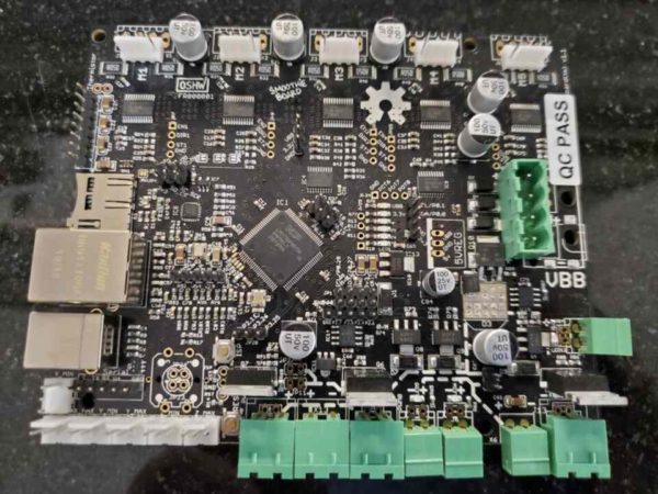
Smoothieware is the name of the company that develops Smoothieware the software and Smoothieboard the hardware. The company tries to support all kinds of machines including 3D printers, laser cutters, CNC routers, CNC lathes, and more. Consequently, Smoothieboards are jam packed full of motor ports, high-power mosfet ports, thermrister ports, everything. The boards are large and expensive, but they are a great option if you need a single integrated solution.
Just keep in mind that over generalization can sometimes be frustrating as it prevents the specialization that makes other tools easy to use. If you’re setting up your smoothieboard to run your CNC router, there will be loads of settings you need to be sure to ignore because they aren’t relevant to your machine.
But some designers want to build a single machine capable of being a 3D printer, a laser cutter, and a CNC router just by changing out the tool. I don’t recommend trying this, but if that is your goal Smoothieware is by far the best option.
Another big pro for the Smoothieboard is that their documentation is very comprehensive. There is a big community of users online, just know that they are mostly in the 3D printer camp.

You can connect a Smoothieboard to the internet with an ethernet cable and it’ll host a little web UI you can access from your laptop to control the router.
It’s a bit light on features, for example there is no 3D graphical display of your tool path, but it should be sufficient to get the job done.
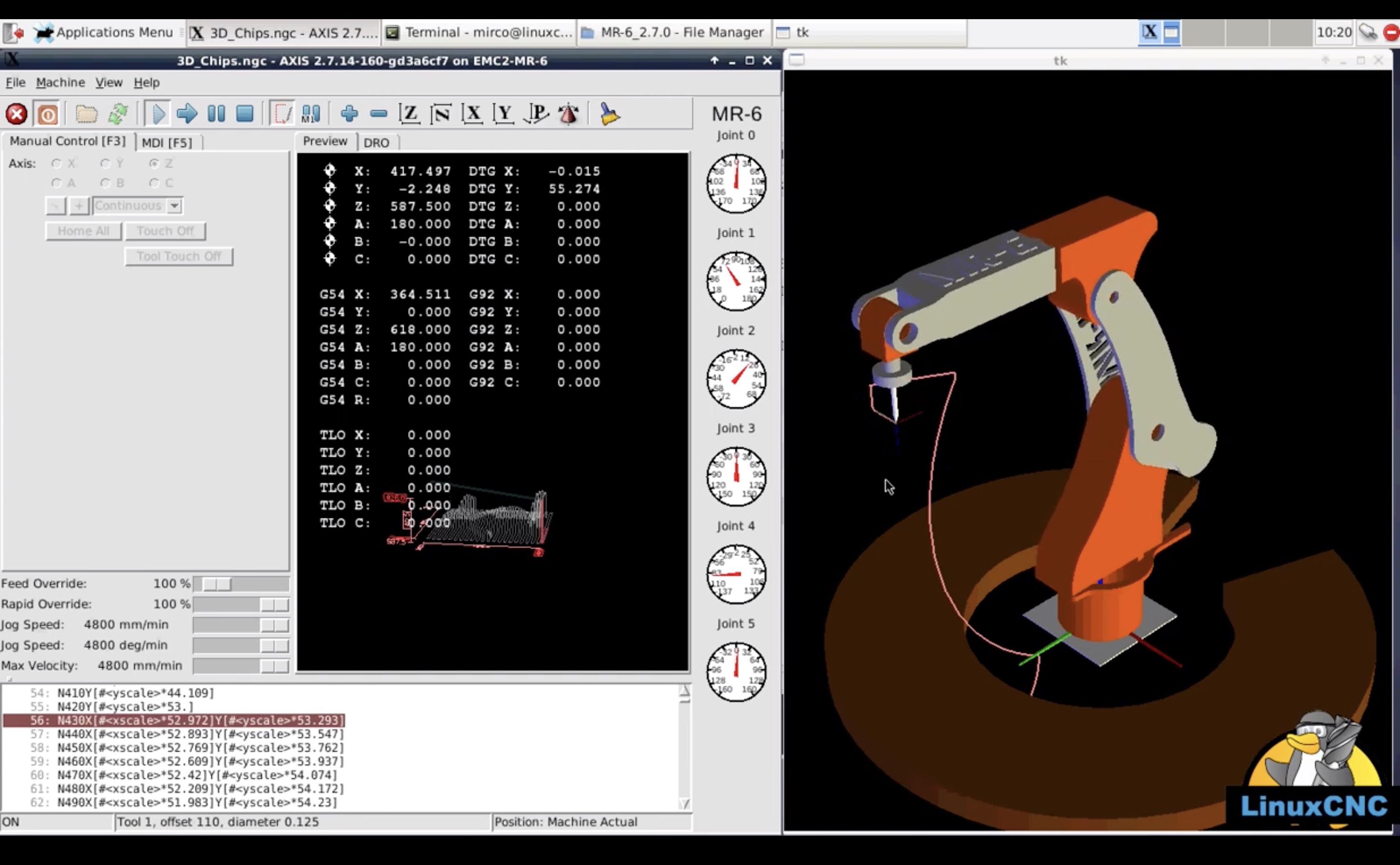
LinuxCNC
LinuxCNC is a distro of Linux that you can install on any PC, even very old ones. The primary idea here is that a full-on desktop computer has many orders of magnitude more resources than a small microcontroller, so it should be capable of controlling a much more complex CNC. You can almost always find an old PC for free on Craigslist and LinuxCNC is free to use, so for many people this is actually the cheapest option!
LinuxCNC is a full-on operating system. It uses configuration files that describe all the parameters of your machine. If you plan to build a simple XYZ cartesian setup, LinuxCNC will be easy to configure from example files.
The super power of LinuxCNC is that it includes an inverse kinematics framework. It can control robot arms, delta configurations, polar configurations*, basically any exotic system you can dream up, you can control in LinuxCNC. The beauty here is that all the complexity of the coordinate transformation lives inside LinuxCNC, allowing it to consume GCode commands in the standard format!
It is also very capable of controlling tool orientation, not just position. This is otherwise known as four, five, or six axis machining.
The main drawbacks of LinuxCNC are complexity and pulse signalling. The complexity problem is that there is just a lot to learn and configure.
Pulse signaling problems come from the fact that most desktop-grade processors running desktop-grade operating systems are not intended for realtime applications. When asked to output a square wave of exactly 10 MHz, most processors will emit some jitter, sometimes switching just a little too late. LinuxCNC does offer a realtime variant but it is not guaranteed to work on every machine. Furthermore, even if your processor can generate a stable signal, the only way for it to get that value out is over a parallel port, which is absent on all modern desktops.
In practice, almost everyone using LinuxCNC on a desktop pairs it up with a Mesa board purpose built to do pulse generation. LinuxCNC then communicates over Ethernet or PCIe to the dedicated card, sending high-level commands which are translated into pulses. This greatly alleviates the workload on your desktop and guarantees very stable pulse signaling to your motors.
So in practice, LinuxCNC is the “all-in-one” software package that almost inevitably needs to be connected to a purpose-built pulse generation card, which needs to be connected to a driver card that can power your motors. Sometimes the pulse generation and driver cards are combined in to one. It’s on you to research which cards are compatible with your computer and with each other. Expect to spend $100-$300 on the add-on cards.
LinuxCNC also provides a variety of different GUIs at varying levels of polish. Some of these are optimized for touch screens, making for a very shop-friendly experience.
*I don’t know if LinuxCNC is the controller for this robot or not, the video is just illustrative of novel kinematics
Mach3/Mach4

Mach3 and its successor Mach4 are Windows-only software packages that are similar to LinuxCNC.
Compared the LinuxCNC, the advantages of Mach4 are:
- You can buy hands-on support to help you get set up or to fix bugs
- The setup process is friendlier for people who don’t know much about software or Linux
- Seems to be more popular in the running-an-actual-shop category of users
The disadvantages are:
- Mach4 costs money
- It expects to run on more modern hardware
- It does not contain a general purpose inverse kinematics engine
- Runs on Windows only
- Less popular with the cutting edge researchers and garage tinkerers
Both have good user forums, a strong catalog of youtube tutorials, and a long history of online blog posts detailing how to get started. Both require you to buy a separate add-on card(s) manufactured by third party vendors for pulse generation and motor driving. Both systems allow for the use of hardware pendants, z-probes, etc.
Between LinuxCNC and Mach4, which you choose comes down to your attitude. If you’re a busy pragmatist and you’re willing to just pay more money and have it work, go with Mach4. If you’re a curious tinkerer willing to spend a lot of time learning, or if you have no extra money, go with LinuxCNC (or use a GRBL-based alternative).
Spindle
The spindle is the shaft that rotates very fast. It is attached to a big motor on one side and your cutting bit (or a holder that holds your bit) on the other side. For CNC routers, a spindle speed of 10,000-20,000 RPM is standard. For CNC mills, the spindle is generally much slower at 1,000-10,000 RPM, but with significantly more torque.
Technically you could buy the components separately to design your own custom spindle, but that’s extremely rare for CNC routers. Typically you buy an integrated package that contains the spindle, a collet, a motor, a control system for that motor, and a cooling system all integrated into a single product.
Palm Router

By far the most common choice for hobby grade CNC routers, a palm router like the Makita RT0701C or DeWalt DW611 is a great starting spindle.
The big advantages are cost and availability. These routers are usually about $100 and if they break you can run to the nearest home depot and get a drop-in replacement same day. They are also very commonly used by hobbyists so there are loads of resources on optimal feeds and speeds, how to trigger them via GRBL, etc. They are also small and simple and plug directly into the wall.
One big disadvantage is that the collets in these small routers are only capable of holding bits of 1/4 inch shank size. To fit smaller bits you’ll need an adapter sleeve and larger bits just won’t work. The follow on effect of skinny bits is that their lack of rigidity can become a limiting factor on the accuracy of your cuts, as can the runout of the router, which is just not designed to be a high precision tool.
Another big disadvantage is noise. It seems like a non-issue at first, but when you’re pulling a 10 hour job and you can’t escape the incessant whining of the router, you may regret taking the cheap, noisy option. On the topic of long-running jobs, palm routers are not designed to run continuously for hours at a time so you may end up with overheating issues if you run for too long. I have run my Makita RT0701C for 10 hours at a time and by the end it is very hot.
The last disadvantage worth mentioning is that palm routers are not designed to have their speed controlled by an external controller. To get your GCoder interpreter to control the spindle speed you’ll need to open it up and do some rewiring, which can be daunting or downright unsafe if you don’t already know what you’re doing. Most hobbyists instead use a relay-controlled AC power strip so that your GCode interpreter can just switch the router on and off, rather than giving full speed control.
Air Cooled Spindle

Air cooled spindles are generally much more performant than the palm routers. They tend to have much more powerful motors with better speed control, the spindle itself has much less runout, and the tool holder has a much bigger, more general purpose collet. Some spindles even support automatic tool changing, and all of them are designed for continuous output for many hours at a time.
Spindles are usually based on brushless motors rather than brushed, so while a palm router might need its brushes changed after 1000 hours of use, a spindle would be expected to keep working 10 times as long before needing any maintainence.
Their drawbacks are higher cost ($300-$600), long lead time because you usually have to order one from China, and much heavier weight, usually 3x higher than a palm router. Another drawback is that the control electronics live in a separate box that needs to be stored somewhere on your machine. If you really want the highest performance out of your machine, buy a real spindle.
Water Cooled Spindle

Water cooled spindles are identical to air cooled spindles, but they require you to buy and run a separate water-based cooling system. This can be a messy undertaking, but the benefits of water cooling are twofold:
The first is that your router can run indefinitely. This is important if you’re building a huge system that will carve detailed 3D shapes onto whole 4’ by 8’ sheets of wood, as doing this takes days of CNC time.
The second big advantage is low noise. Water cooled spindles are exceptionally quiet compared to air cooled spindles or palm routers.
DC Spindle

Beware of any DC spindles you find. These are typically extremely low quality devices made to look similar to real spindles but they are much smaller with just a fraction of the output power.
From what I can tell, these are meant to trick people into thinking they are buying high quality spindles while in fact giving you the lowest quality product imaginable. If you see a spindle with just a red and black wire coming out of it, or if you see a spindle for less than $200, it is likely not worth buying.
Work Holding
Holding your work securely is incredibly important. It doesn’t matter how good the rest of your machine is—if the work is held poorly, the results will be poor.
Fixing Directly to the Spoilboard

A Spoilboard is a single sheet of dimensionally stable material, usually MDF, that you can fix your work to directly. You can screw, nail, or clamp the work piece directly onto the spoilboard to create a rigid connection. This does some damage to the spoilboard, but MDF is so cheap that you just use it until it the damage is starting to get in your way, then you make a new spoilboard. Another technique is to deliberately use a thicker spoilboard than you need at first, then instead of replacing the entire MDF sheet you can just use the CNC router to take a layer off the top, giving you a freshly flattened surface to work on.
The main idea behind a spoilboard is that it wears out and you replace it. Some people cut their spoil board into many thin strips so that they only need to replace a few if only a few are damaged. Some people fashion a cutting surface out of many small tiles of MDF so they only have to replace the individual tiles that are damaged. These are all considered spoilboard, just different approaches.
The biggest advantage of directly fixing your work piece to spoilboard is that you have no extra work holding hardware to worry about accidentally crashing your spindle into.
This is an incredibly popular design for CNC routers. Unless you have a specific reason to avoid spoilboard, you should probably incorporate one into your design.
T Track and Clamps

T Track is a type of metal channel that lets you fix clamps and stops in place just by screwing them down. These are very helpful if you need to make repeatable jigs for manufacturing large numbers of parts, and generally don’t get damaged with use.
The big disadvantage of T Track for work holding is that you inevitably end up with clamps on the work surface that the cutting bit needs to avoid. This requires lots of planning and foresight on your part so that you don’t mistakenly destroy your clamps or worse, destroy your spindle. This can be eased somewhat by modeling your clamps as part of your setup in your CAM software, but that too takes time and effort.
A second disadvantage is that many CNC routers just don’t have much z-axis clearance from the work surface to the gantry. If you have tall clamps, a thick spoilboard in place, or a particularly thick work piece, the clamps can get caught on the gantry. All this requires further planning or modeling on your part to avoid, which can be a real headache.
Many designs combine spoilboard and T track together by using thin slats of spoilboard between the tracks. This offers you the flexibility to use one or the other depending what you’re cutting.
Machinist Vise

If you really need high precision, repeatable, extremely rigid work holding then a machinist vise is a great choice. The biggest downsides are cost and clearance. A good machinist vise is about $1000 and most CNC routers lack the gantry clearance to fit a vice. But if your CNC router is more of a CNC mill in terms of rigidity, axis arrangement, and material to cut, a vice might be for you.
Dust Collection
CNC routers kick up a lot of dust and chips. These get everywhere, making a huge mess and making you cough. While it is technically optional, you will want to seriously consider your dust collection solution during the design stage rather than tacking one on at the end when your machine is built.
Vacuum Boot

Vacuum boots can eliminate a ton of dust but they usually don’t get it all. Their big advantages are that they are cheap to get ahold of, easy to remove, and only require you to own a shop-vac.
The big disadvantages are imperfect dust collection, and that the boot can sometimes get in the way with the part you are trying to cut. Imagine cutting a deep, conical pocket in a solid block of wood. There is just no way for a dust boot to accomodate this while still being effective. For shallow cuts over large areas though, a dust boot is a fantastic choice.
Enclosure

Enclosures are cages that trap all the dust and chips. You can make one out of wood, plastic, metal, even cardboard.
The best things about enclosures are that they can often reduce the sound of your router substantially. They also offer fantastic dust protection and will never get in the way of your cuts.
The disadvantages are that they are big and expensive, sometimes feeling like entire projects unto themselves. They also complicate the ergonomics of using your router, especially if you nail your work pieces directly to spoilboard, or need to change tools often.
Axis Arrangement
The overall layout of your machine’s frame will make a big impact on what your machine can do.
Sliding Gantry

Almost all large CNC routers are sliding gantry designs where the work piece stays completely still, with a sliding gantry that holds the spindle. In these designs, the x, y, and z axes are in a way stacked on top of each other in series.
One problem with triple stacked designs can come from cable routing to power the motors and sense the end stops because they all move. You need to be sure that there is no way for the machine to yank out its own power, for flying debris to cause a short circuit, and you need to be sure that the electrical noise from the power wires doesn’t accidentally trip the end stop circuits. This means careful planning, cable tracks, and strain relief. Also twisted pair wiring everywhere if not full on optically isolated switches. Obviously these are concerns no matter what your overall layout, but triple stacked designs have it the worst of any.
Further problems include paying a rigidity penalty. With each stacked axis, slop is compounded and lever arms get longer. It is possible to stack three axis which are each on their own sufficiently rigid, and still end up with a final product which is insufficiently rigid. For this reason whenever you see a high quality sliding gantry machine in person, it always seems overbuilt from thicker, more expensive material than you might guess is necessary.
Despite the added design complexity, sliding gantry is the only practical way to accommodate very large bed sizes because the floor footprint of the machine need only be as large as the working envelope, plus a small buffer on all sides. If you want to cut 4’ by 8’ sheets in a real shop where space is at a premium, this is essentially the only way.
On a sliding gantry the spindle is 3 moving axes away from the frame.
Fixed Gantry

Fixed gantry designs are very popular with small desktop CNC routers and 3D printers. Moving the work piece on just a single axis is a great compromise because it reduces the stacked-axis problems significantly, simplifying the design and resulting in a lighter-weight machine. The drawback is that the footprint of a fixed gantry machine must be larger than the working envelope by a factor of 2! For that reason alone, you don’t see many large machines with this axis arrangement.
On a fixed gantry the spindle is 2 moving axes away from the frame.
Column Mill

Benchtop mills are typically laid out as column mills. In these designs the central feature is a frame consisting of a single tall column on which the spindle rides up and down. At the bottom of the column are the x and y axes stacked on top of each other, with the work piece stacked on top of that.
When designed with care, the column mill layout is excellent for rigidity, which means you can more easily achieve great surface finishes on harder metals, you can take deeper cuts, and you can make the most of a beefy spindle. There is a reason small mills are laid out this way, and that reason is rigidity.
The major drawback is how much floor space these designs take up for how small of a working envelope they provide. If you are going this route you should probably consider your design a CNC mill rather than a router—you are starting to blur the line.
On a column mill the spindle is 1 moving axis away from the frame.
Knee Mill

A knee mill is an axis layout where the spindle is completely fixed to the frame, while the work piece moves around on all three axes. This is the most rigid design I know of, with the only real drawback being that the working envelope is much smaller than the footprint of the machine on the floor. If you wanted a 4’ by 8’ working volume, you would need at minimum an 8’ by 16’ floor footprint.
Because it is so rigid but scales up so poorly, these designs are almost exclusively used for metal mills which have relatively small working envelopes compared to CNC routers. It is not practical to build a CNC router this way, because in CNC routing you are usually working with relatively soft materials and your parts are usually relatively large.
On a knee mill the spindle is 0 moving axes away from the frame.
Cutting Tools
To achieve most projects you will need multiple cutting tools. These can be bought in kits or starter sets, but all you really need at first are listed here.
If this is your very first experience with CNC then buy the cheapest bits you can find because you will certainly screw up and run your bits into things, inevitably breaking a few in the process while you learn how to better control the spindle. If you can make a single cheap bit last long enough that you start to feel its limitations, then go ahead and splurge on a high-quality, big-name equivalent.
The most important properties to consider in any bit are the material it is made of, the thickness of the shank, and the cut direction.
The big material choice is carbide vs high speed steel. If you are cutting lots of wood it won’t matter which you choose. If you are cutting aluminum, high speed steel will probably perform better for you. If you are cutting steel, carbide will probably perform better for you. There are many different colored coatings that some manufacturers apply but I suspect these are just marketing hype.
The shank is the part of the tool where the spindle grips it. You want to use the thickest-shank tool you can in any particular operation because it maximizes rigidity to have a thicker shank. For palm routers that limit is often 1/4 inch. For bigger spindles 1/2 inch is available.
The cut direction does not refer to if the bit cuts spinning clockwise or counterclockwise. All bits are intended spin the same direction and many spindles can only spin in that direction. Cut direction refers to the direction that chips are evacuated from the cut. Up-cut bits have flutes shaped in a spiral that grabs and pulls chips up and out of the pocket that you are cutting, like a standard drill bit. These leave a great surface finish on the bottom but on many woods in particular, this leaves an untidy mess at the top of the part that will need to be cleaned later. The opposite is a down-cut spiral bit that forces chips down into the cut. This leaves a clean finish on the top surface of your part but a poor finish on the bottom. A more exotic option is the compression bit which is shaped so that the very bottom of the bit is an up-cut bit but the rest of the bit is a down-cut bit—a compromise that gives the advantages of both provided your depth of cut is deep enough. Lastly are flat bits which don’t spiral at all—a compromise that sits right in the middle ground. Flat bits are more rigid and can consequently be made longer with the same cutting performance for cutting deep pockets.
Flat Nose

This may well be your most-used bit. The flat nose means it can clear large areas leaving behind a smooth flat surface, and that it can cut sharp-bottomed corners. For large amounts of material removal, this is a fantastic default bit.
The biggest drawback of this bit is the relatively fragile tips which if chipped, ruin the whole bit.
You may notice that the cutting surface is not actually flat, but comes to a very shallow ‘v’ on top. This is intentional and helps flat nose bits make cleaner cuts. Don’t worry, it will not leave any ‘v’ shaped groves on your finished part!
If you are on a palm router, start by buying an up-cut flat nose bit made of carbide, in the maximum shank diameter that your router can hold, likely 1/4 inch. If you want to be able to cut tighter inside corners, buy a 10-pack of the smaller 1/8 inch bits and a set of adapter sleeves so they can be held in your router’s collet.
Ball Nose

A ball nose bit is just like a flat nose bit except it has a rounded nose. This type of bit is very helpful for cutting fillets and for cutting irregular contours such as a 3d model of a face. The ball nose bit lacks sharp, fragile corners making it tougher and better equipped to remove material more aggressively than a flat nose bit. Some people will use a ball nose bit to clear tremendous amounts of material away as a preparatory step before using a different bit to cut the part to final dimensions.
A single large ball nose bit is probably enough to get you by on material clearing, but the real value is in carving intricate surface details using a small radius ball nose bit. For that you’ll want to find a tapered ball nose that starts out at the full 1/4 inch thickness and tapers down to something like 1/16, ending in a 1/32 radius ball nose. In both cases up-cut and carbide are fine defaults.
Spoilboard Surfacer

If your design includes a spoilboard it will be critical to flatten it before use. This is typically done using the router itself, programmed in a back-and-forth path to cut a consistent reference height into the possibly-uneven surface. Clearing a large spoilboard with a small bit is a pain, so you can use a spoilboard surfacing bit to remove huge amounts of material very quickly.
A typical spoilboard surfacing bit might clear 1” at a time, up from the 1/4” flat nose bit you might otherwise be stuck using.
Engraving

An engraving bit is shaped like a V, typically at 90 degrees or 60 degrees full angle. They cut V’s into the material, which is very common in sign making. You can use this type of bit to write letters and numbers, draw stylized designs, cut chamfers, and countersink holes. A bit like this is also critical for v-carve inlays, which are a popular type of art made with CNC routers.
Others
There are thousands of different types of bits available. Solid manufacturers include Amana tool, Whiteside, and Kennametal. Check out their websites to learn about all the different specialty bits and how they can help you with your project.
Usability Improvements
Designing and building a CNC router is only the first step. If your goal is to actually use your CNC router, there are a few quality of life improvements to keep in mind.
Z Axis probe
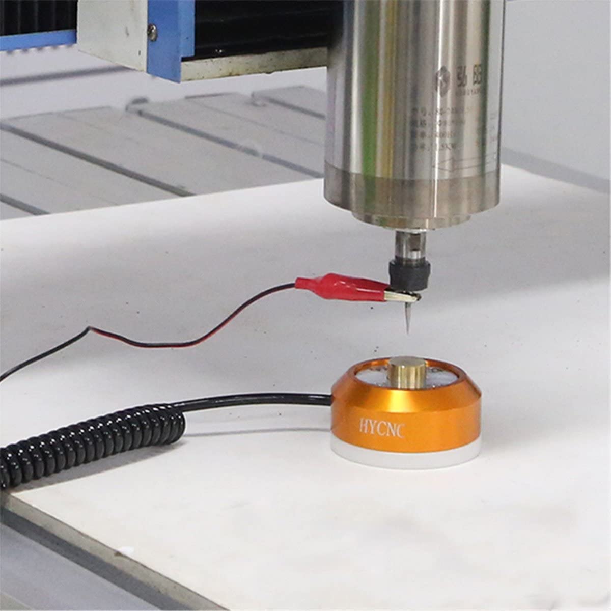
Every time you change tools, the height will be slightly different. You’ll have to manually find the new height of the tool, a process usually involving a sheet of paper and some trial and error. While the manual approach is not difficult, it gets extraordinarily tedious if you have many tool changes per job, and many jobs to run.
A z-axis probe measures the electrical conductivity of a circuit that runs through the cutting tool down into a metal plate that you fix onto the spoilboard. The CNC controller can automatically lower the height of the cutting tool until electical contact is made, accurately and repeatably determining the height of the tool. This requires some setup in hardware and software, but it a huge time saver in practice.
If you don’t want to deal with this at first that’s okay, they are easy to add to existing machines later on.
Automatic Tool Changing

Automatic tool changers do exactly what their name suggests. You can have a fixed library of tools assigned to tool holding slots, and the machine can be made to switch between them whenever it needs to. This is incredibly convenient for complex jobs, jobs that are very long running, and jobs that you have to repeat over and over.
Generally hobbyists do without, but if you’re thinking of starting a small business around your router then you should definitely consider adding an ATC. It is usually somewhat difficult to add an ATC to an existing CNC router, but then again it is also difficult to design one in from the start. ATCs can only work with spindles that support quick change tools.
ATCs add cost, but they make up for it in saved time.
Conclusion
There are many components to consider when designing your CNC router. From the frame to the linear actuators to the cutting tool itself, at every step of the way remember that rigidity is king.
Contact me
If you have questions about your CNC router, feel free to message me on twitter and I will do my best to reply. I’m also available at mattferraro.dev@gmail.com.